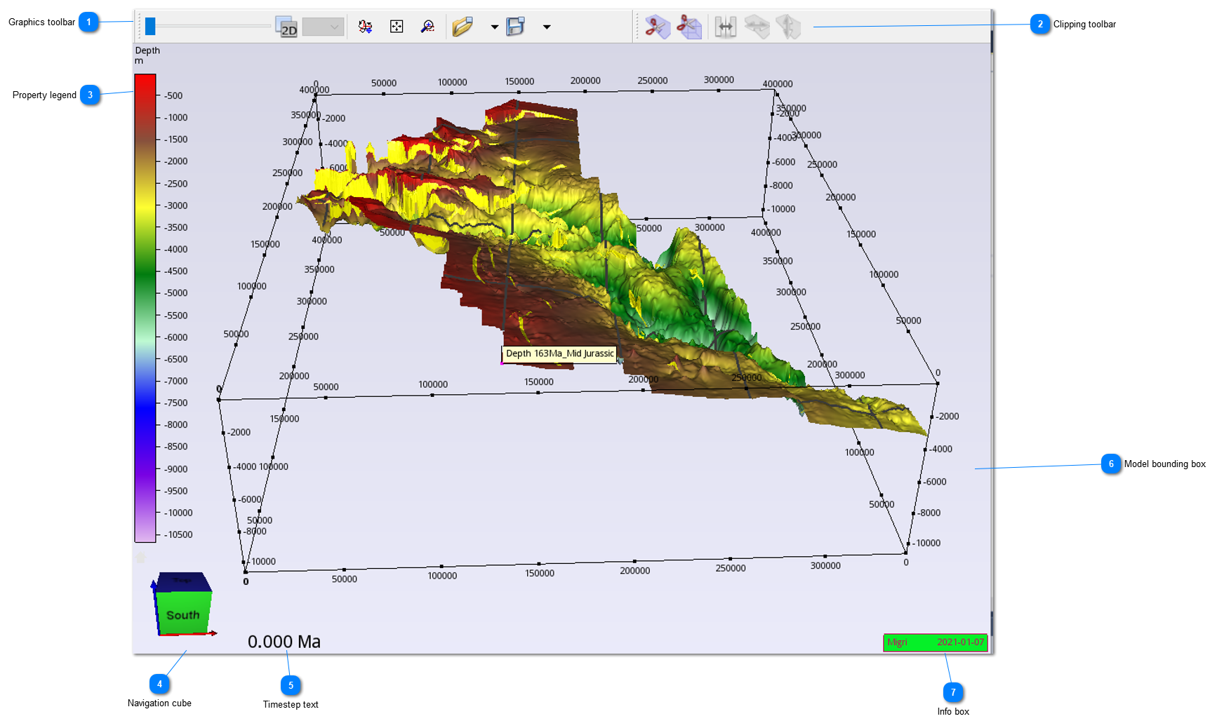
The 3D view window is at the centre of the MigriX user interface and it is the only part of MigriX that cannot be made invisible, with the exception that it can be used in two modes: a 3D view mode (Figure 5.2) or a 2D view mode. In 2D mode, the properties of a single layer / sub-layer are shown.
The layer is chosen by picking in the Layers of the Project Workspace panel, while the sublayer is chosen from the list to the right of the 3D/2D button in the Graphics toolbar. This list is only visible when the 2D view mode is active. View canvas elements such as legend, title, navigation cube and model bounding box can be turned on or off from the view menu.
Figure 5.2:3DView elements and graphics toolbar.
Graphics toolbar
The Graphics toolbar provides functionality for interacting with 3d view, such as stretching the model, changing the viewpoint and rotating. The 2D/3D button changes between single layer 2d view and multi-layer 3d view.
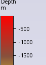
Legends for the currently active properties in the 3dview. Can be turned on or off in the View/Layout menu. Font sized can be changed in File/Preferences.
The geomodel shown in the 3D view can be moved <LMB>, rotated <LMB> and moved closer or further away (<LMB + RMB>).
Once a point has been picked, actions can be selected from the menu that will appear when the <RMB> is pressed down. Depending on the availability of the data, the <RMB> menu can be used to:
Set contouring range for the property legend
Show information about the point in the 3D window and in the Selection info panel
Plot trap history statistics in the TrapViewer for the trap of the picked point
Toggle visibility modes for model layers and gridmaps.
Figure 53:Right Mouse Button <RMB> menu in the 3D view window. The menu is context sensitive and available options will depend on state of model.
Picking of one or more points is done by holding down the control button <CTRL> and pressing <LMB> for each point. Single- or multi-point selection is done by the leftmost button in the Selection Info toolbar. The toolbar buttons can be used together with the the Selection Info window to digitize polygons or point data and store the points to file. When points are picked in the profile window, they will also be shown in the 3D view window. When points are picked on profiles in the 3D view window, they will be shown in the profile window.
Layers can be made visible or invisible by setting the visibility option in workspace/property after selecting one or more layers in workspace/layers. The same effects can be achieved more easily by use of the <CTRL + RMB> option while hovering the mouse over a layer in the 3D view. From the full list of options we emphasize:
· Select layer: <LMB> - Click on the layer to be selected.
· Deselect layer(s): <LMB> - Click outside of the layers.
· Hide layer: <CTRL + RMB> - Click on the layer to be hidden.
· Hide other layers: <CTRL + ALT + RMB> – Click on layer to remain visible
· Show all layers: <CTRL + RMB> - Click outside of the layers.
· Select node: <CTRL + LMB> - Click on the node to be selected.